
- Product Details
- Related Products
- Contact Us
1.Introduction
CM series MPPT controller is an advanced, efficient and versatile photovoltaic product. It uses innovative maximum power point tracking technology to significantly improve the energy efficiency of solar energy systems with a conversion effciency of 97%. The controller adopts intelligent battery charging management and has temperature compensation function to effectively manage the battery and extend the battery life. The controller integrates RS485 communication interface, which can provide communication protocol, which is convenient for customers to integrate and manage.

2.Main Features
1. Intelligent maximum power tracking technology
2. High precision and high effciency with DSP chip control
3. The PV wide range voltage input , three s tage charging technology The photovoltaic/battery connection reverse protection
4. short-circuit protection /over current protection
5. Display technology parameter with 7 inch touch screen Rs485 remote communication and data transmission(optional)
3.Application Diagram

4.Technical Data
Model: MP- 20 / 30 / 40 / 50 / 60 | 20 A | 30 A | 40 A | 50 A | 60 A | |
Charging Mode | MPPT Automatic Maximum Power Point Tracking | |||||
Charging Method | Three stages : Constant Current ( MPPT), Balanced Charging, Floating Charge | |||||
System Type | 12 V/ 24 V/ 48 V | Automatic Identification/ Manual Setting | ||||
System Identification Voltage Range |
12 V System |
DC 9 V- DC 15 V | ||||
24 V System | DC 18 V- DC 30 V | |||||
48 V System | DC 36 V- DC 60 V | |||||
Soft Start Time | 12 V/ 24 V/ 48 V | ≤10 s | ||||
Dynamic Response Recovery Time |
12 V/ 24 V/ 48 V |
≤500 us | ||||
Static Power | 12 V/ 24 V/ 48 V | ≤2 W | ||||
Machine Efficiency | 12 V/ 24 V/ 48 V | ≥96 . 5 % | ||||
PV Module Utilization | 12 V/ 24 V/ 48 V | ≤99 . 97 % | ||||
Input Characteristics | ||||||
MPPT Operating Voltage Range | 12 V System | DC 18 V- DC 150 V | ||||
24 V System | DC 34 V- DC 150 V | |||||
48 V System | DC 65 V- DC 150 V | |||||
Input Low Voltage Protection Point | 12 V System | DC 16 V | ||||
24 V System | DC 30 V | |||||
48 V System | DC 60 V | |||||
Input Low Voltage Recovery Point | 12 V System | DC 18 V | ||||
24 V System | DC 34 V | |||||
48 V System | DC 65 V | |||||
Limit Input Voltage | 12 V/ 24 V/ 48 V | DC 160 V | ||||
Overvoltage Protection | 12 V/ 24 V/ 48 V | DC 150 V | ||||
Overvoltage Recovery | 12 V/ 24 V/ 48 V | DC 145 V | ||||
Maximum Solar Panel Input Power | 12 V System | 280 W | 420 W | 570 W | 700 W | 900 W |
24 V System | 550 W | 840 W | 1130 W | 1400 W | 1700 W | |
48 V System | 1100 W | 1650 W | 2270 W | 2800 W | 3400 W | |
Output Characteristics | ||||||
Optional Battery Type (Default is l e a d - acid maintenance- free battery) |
12 V/ 24 V/ 48 V | Lead- acid maintenance- free Battery, G e l Battery, Liquid Battery, Lithium Battery ( Can also be customized for other types of battery) | ||||
Technical Parameters
Model: MP- 20 / 30 / 40 / 50 / 60 | 20 A | 30 A | 40 A | 50 A | 60 A | |
Flo ating Charge Voltage ( lead Acid Battery) | 12 V System | 13 . 75 V( Can be customized) | ||||
24 V System | 27 . 50 V( Can be customized) | |||||
48 V System | 55 . 00 V( Can be customized) | |||||
Average charging Voltage ( Lead Acid Battery) | 12 V System | 14 . 20 V( Can be customized) | ||||
24 V System | 28 . 40 V( Can be customized) | |||||
48 V System | 56 . 80 V( Can be customized) | |||||
Rated Current | 12 V/ 24 V/ 48 V | 20 A | 30 A | 40 A | 50 A | 60 A |
Current Limiting Protection | 12 V/ 24 V/ 48 V | 22 A | 32 A | 42 A | 52 A | 62 A |
Temperature Coefficient | 12 V/ 24 V/ 48 V | ±0 . 02 %/ ℃ | ||||
Temperature Compensation | 12 V/ 24 V/ 48 V | 14 . 2 V-( M a x i m u m Temperature - 25 C) * 0 . 3 | ||||
Output Regulation Accuracy | ≤± 1 . 5 % | |||||
LCD Display | D e t a i l s in LCD Display Instruction | |||||
LED Display | Charging I n d i c a t i o n , DC O u t p u t Switch Status Indication | |||||
PC Host Computer | Rs 485 ( Optional) | |||||
Protection | ||||||
Input Low Voltage Protection | Reference Input Characteristics | |||||
Input High Voltage Protection | Reference Input Characteristics | |||||
Input Polarity Reverse Connection Protection | Available | |||||
Output Polarity Reverse Connection Protection | Available | |||||
Short Circuit Protection | After 5 trial starts will enter the protection state, Restart Recovery | |||||
Temperature Protection | 85 ℃ | |||||
Temperature Rise Protection | Reduce Power O u t p u t When Exceed 80℃ | |||||
Other Parameters | ||||||
Noise | ||||||
Heat Dissipation Method | Forced air cooling, fan speed is adjusted by temperature, when the internal temperature is low, the fan runs slowly or stops; when the controller stops working, the fan will s t o p r u n n i n g | |||||
Element | Imported Materials, in line with EU standards,all temperature selection of electrolytic capacitors rated temperature is not less than 105 ℃ | |||||
Smell | Do not release peculiar smell and harmful health smell | |||||
Environmental Requirements | C o n f o r m 2002 / 95 / EC; N o C a d m i u m , H y d r i d e and F l u o r i d e | |||||
PV Module Conguration
System | Battery Voltage | PV module load voltage ( Recomm | ended Value) | ||
12 V | System | 18 V~6 0 V ( 30 V module* 1 s t r i n g , 36 V | module* 1 | string) | |
24 V | System | 36 V~72 V ( 30 V module* 2 string, 36 V | module*2 | s t r i n g ) | |
48 V | System | 72 V~144 V ( 30 V m o d u l e * 3 string, 36 V | module*3 | string) | |
-
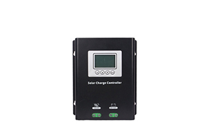
ORI-SCP PWM series charge controller
Based on an MCU intelligent control technology, Itrealizes solar charge and discharge management for batteries for longer lives of systems.It is widely applied to the solar power systems for families, schools, streets, industrial etc.. -
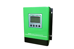
ORI-CM-MPPT charge controller
ORI-CM-MPPT seriescontroller is an advanced, efficient and versatile photovoltaic product. It uses innovative maximum power point tracking technology to significantly improve the energy efficiency of solar energy systems with a conversion efficiency of 97%.